As electrification accelerates, engineers face a recurring challenge: how to safely and efficiently manage high current loads? Whether it’s powering an e-bike, driving a forklift or running an industrial tool, designers often end up paralleling MOSFETs to meet current demands. While simply adding devices in parallel seems easy enough, real-world implementation demands a deeper understanding of dynamic behavior and thermal effects.
When MOSFETs are operated in parallel, slight variations in threshold voltage (Vth), gate charge (Qg) or PCB parasitics can cause individual devices to turn on earlier than others. This results in a current imbalance, where the first device conducts disproportionately, increasing junction temperature and thermal stress. Over repeated switching cycles, this degrades system efficiency, exacerbates thermal cycling and limits the overall reliability of the parallel MOSFET network. Dealing with current imbalance is one of the main reasons engineers approach paralleling with caution. Getting it right means understanding not just the static parameters, but also what happens in the dynamic region.
Narrowing the spread: tighter thresholds, gentler slopes
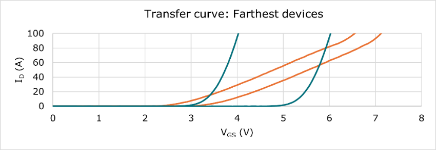
When standard MOSFETs are operated in parallel, Vth differences have a significant impact on how current is shared. Within the same family devices can vary by up to 2 V, and this has only been reduced to around 1 V in newer generations. Particularly in fast switching conditions, the variation is enough to cause one device to turn on slightly before the others, drawing more current and creating an imbalance.

A tighter threshold distribution leads to more uniform turn-on, reducing the likelihood that a single device dominates current during switching. Additionally, devices with lower transconductance (gfs) exhibit a gentler current rise with increasing gate voltage. This softer slope reduces sensitivity to small Vth differences, helping parallel MOSFETs share current more evenly across the operating range.

Stabilizing temperature where it counts
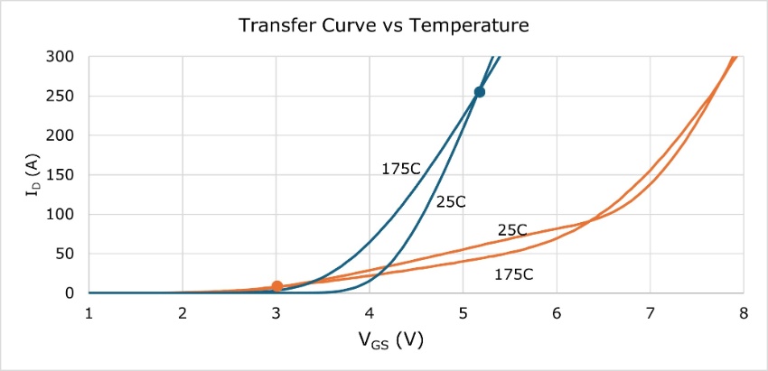
Threshold voltage spread is only one part of the story. Temperature effects also play a critical role. Thermal stability is largely determined by the zero-temperature-coefficient (ZTC) point, where a MOSFET’s transfer characteristics naturally balance current as junction temperature rises. In many standard MOSFETs, ZTC often occurs at currents far above typical operating conditions, often around 250 A. This means that under normal loads, the stabilizing effect of temperature is essentially absent, and current sharing can become increasingly imbalanced as devices heat up.
Lowering the ZTC to a range closer to actual operating currents – for example around 10 A – ensures MOSFETs begin self-stabilizing within the system’s real-world conditions. This, combined with transfer characteristics that remain more consistent across temperature, helps parallel devices share current more evenly. Even across different thermal zones on the PCB.

Quantifying the advantage through real-world testing
Understanding datasheet parameters is important, but the real test comes when devices operate in a switching circuit. In parallel MOSFET tests:
- non-optimized devices exhibited a current mismatch of approximately 10 A at an average peak of approximately 45 A per device.
- ASFETs with dynamic current sharing reduce this mismatch to approximately 90 mA per amp of current.
Another way to quantify this is by looking at the relationship between ΔID and ΔVGS: at 50 A per device. Regular devices can drift apart by roughly 26 A per volt of gate voltage difference, whereas optimized devices reduce this to just under 13 A per volt.

Why this matters
As power systems scale, engineers need components that simplify parallel design while enhancing thermal robustness and dynamic performance. ASFETs optimized for current sharing have been engineered specifically for this purpose. By tightening thresholds, softening transconductance, lowering ZTC and cutting ΔID mismatch, they contribute to more reliable, cooler-running systems and give designers a practical way to parallel MOSFETs with confidence.
Available in 80 V and 100 V LFPAK88 packages, these ASFETs integrate seamlessly into compact, high-power designs - empowering engineers to build systems that share better and last longer.
Explore Nexperia’s ASFETs with enhanced dynamic current sharing to simplify your next high-current design.